
2024 year:
Awaiting the fifth telescope
The Director of the Joint Institute for Nuclear Research in Dubna, G.V. Trubnikov, visited the Laboratory of Nuclear Problems together with Academician of the Russian Academy of Sciences G.A. Zherebtsov. They familiarized themselves with the gamma telescope of the TAIGA installation, which is being prepared for shipment to the field site. The project leader, A.N. Borodin, provided a detailed account of the work progress and preparations for the experiment.
Four telescopes have already been installed at the astrophysical field site, three of which are operational. Currently, preparations are being finalized for the shipment of ACT-5, the fifth telescope of the TAIGA experiment. It will soon be sent to the Tunka Valley.
Photo: JINR Director G.V. Trubnikov, Director of the Institute of Solar-Terrestrial Physics SB RAS G.A. Zherebtsov, A.N. Borodin, D.V. Naumov in the fifth building of the LNP.
© Based on materials from the JINR Information Policy Department
2023 year:
Installation of a small experimental cherenkov telescope
At the end of November, a lens telescope with a matrix of silicon photomultipliers was installed by employees of the Institute of Applied Physics of ISU, as well as MSU and JINR.
It is known that one of the disadvantages of the joint operation of the TAIGA-HiSCORE installation and the TAIGA-IACT telescopes is the significant difference in apertures. The aperture of the IACT is 20 times smaller than the aperture of the TAIGA-HiSCORE installation, and accordingly, only 5% of the events registered by the TAIGA-HiSCORE installation fall within the field of view of the IACT.
Small experimental Cherenkov telescopes are planned to be used for studying the energy range above 50 TeV with cameras having a 15-degree field of view diameter. When operating such telescopes, the percentage of events jointly detected with the TAIGA-HiSCORE installation will increase by a factor of 10, and for joint events, the high efficiency of selecting events from gamma quanta will be maintained.
Defense of the candidate’s dissertation
Congratulations to Roman Monkhoev, a junior researcher at the Institute of Applied Physics of ISU, on successfully defending his candidate’s dissertation titled “The Tunka-Grande Scintillation Installation for Studying Cosmic Radiation in the Energy Range of 10^16 – 10^18 eV: Creation and Results” in the specialty 1.3.15 “Physics of Atomic Nuclei and Elementary Particles, High Energy Physics.”
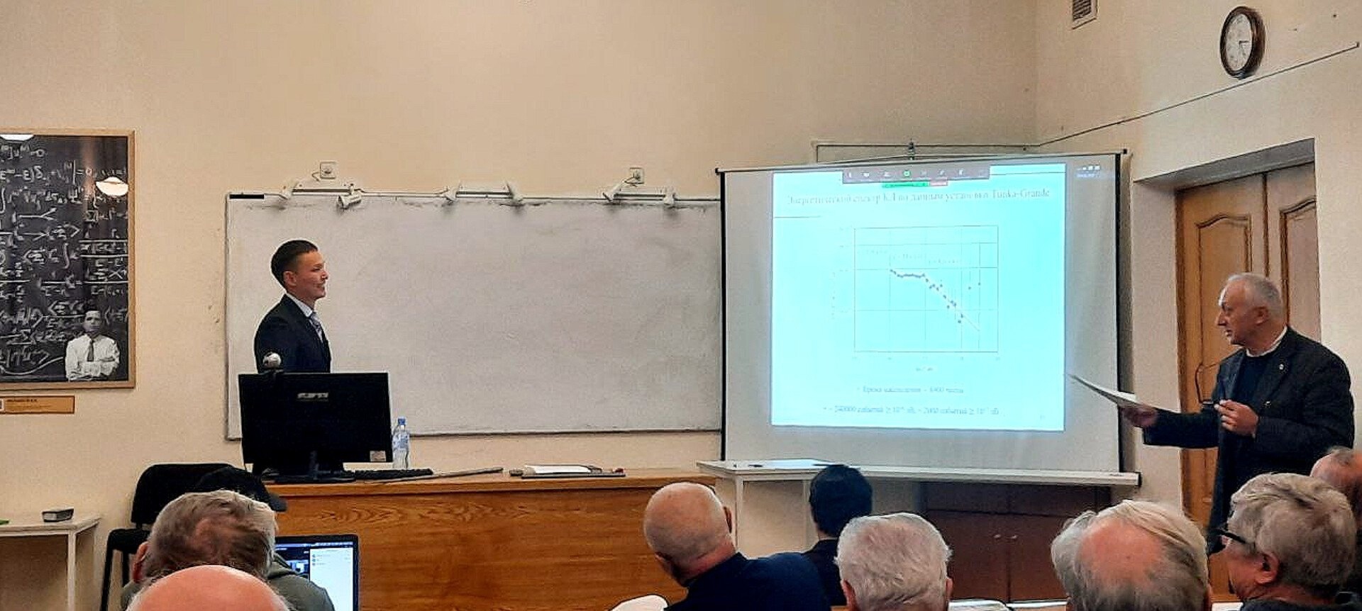
The work was presented on December 8 at the dissertation council of Lomonosov Moscow State University (MSU.013.2(01.11)).
We wish him a swift and confident journey from candidate to doctor of science!
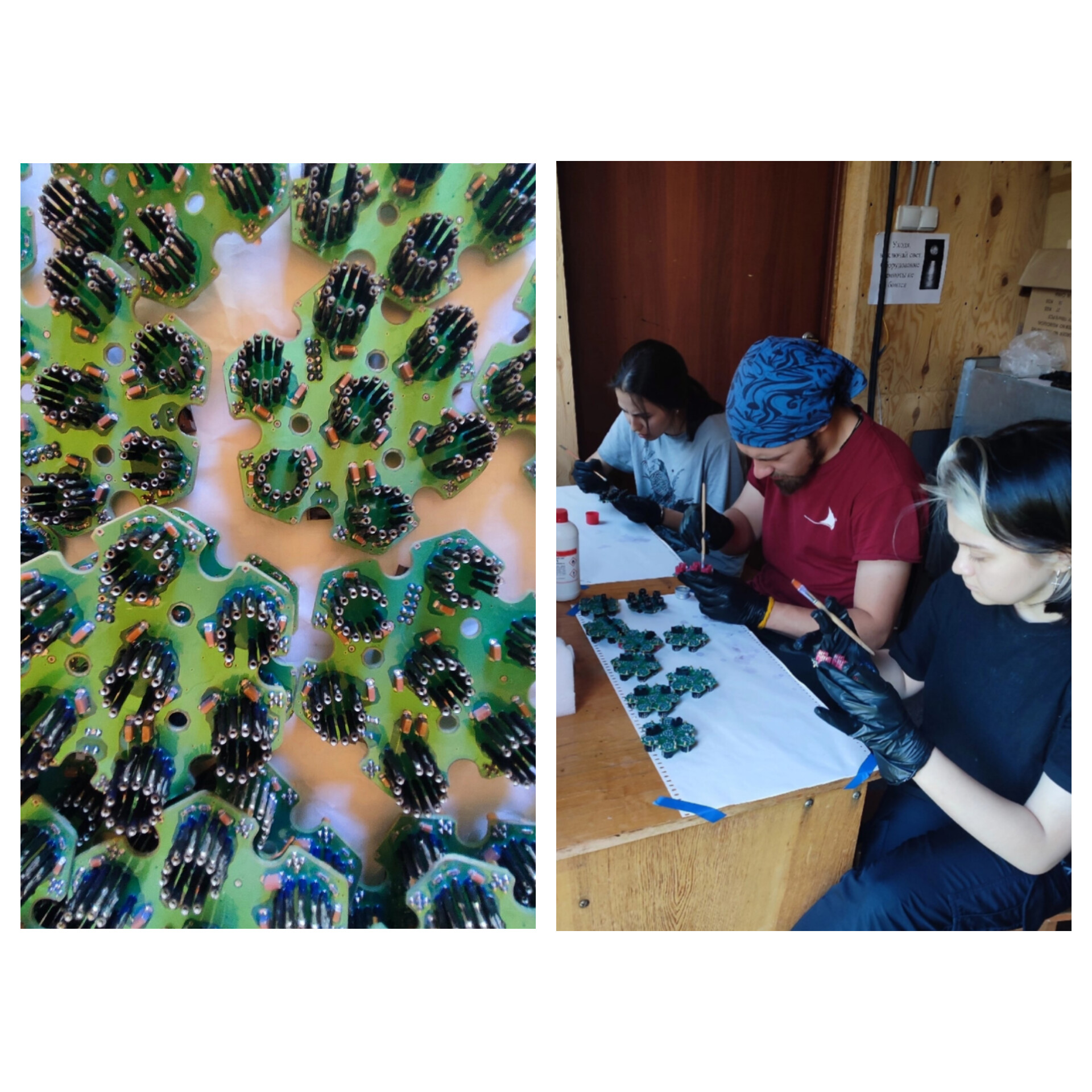
Specialists from the BINP SB RAS and NSU have designed scintillation detectors for the TAIGA
These detectors are essential for studying cosmic rays and gamma astronomy. Some of the new devices are ready, but in total, they need to assemble 200 detectors. The assembly is taking place right in the university’s laboratory.
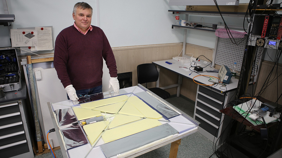
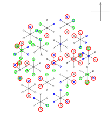
“We have created a fairly unique modeling system at the intersection of astrophysics and particle physics. Thanks to the modeling program we developed, we were able to find the optimal number and arrangement of detectors to most accurately register atmospheric showers…”, said Evgeny Kravchenko, the head of the NSU laboratory and a senior researcher at the Budker Institute of Nuclear Physics SB RAS.
Read more about the laboratory’s work and the “TAIGA” experiment in the NSU article: https://www.nsu.ru/n/media/news/nauka/
Teamwork is the key to success in any project
Having fun and working together to install mirrors on the 4th image atmospheric Cherenkov telescope.
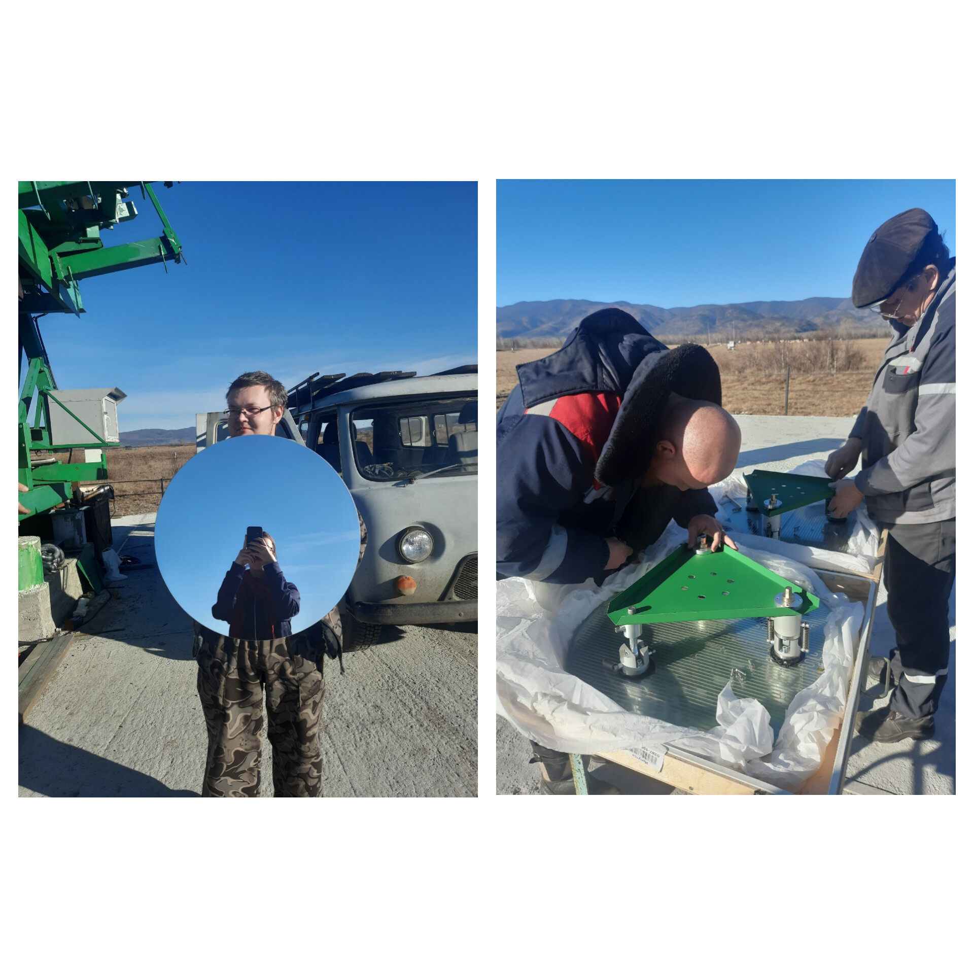
Photo: Ekaterina Kisteneva
Best article in the “Bulletin of the Russian Academy of Sciences. Physical Series” journal
The article by Monkhoev R.D., “Main Results of the Tunka-GRANDE Experiment,” on behalf of the TAIGA collaboration, has been selected as the editor’s choice in the thematic issue “Physics of Cosmic Rays” according to the decision of the editorial board of the journal “Bulletin of the Russian Academy of Sciences. Physical Series”: izv-fiz.ru/ru/redchoice/
Congratulations to Roman and all members of the collaboration on this achievement, and we wish you further success!
PhysicsA.SPb conference
From October 23 to 27, the international conference PhysicsA.SPb-2023 was held in St. Petersburg, organized by the Ioffe Institute, with a large delegation from the Institute of Applied Physics of ISU participating.
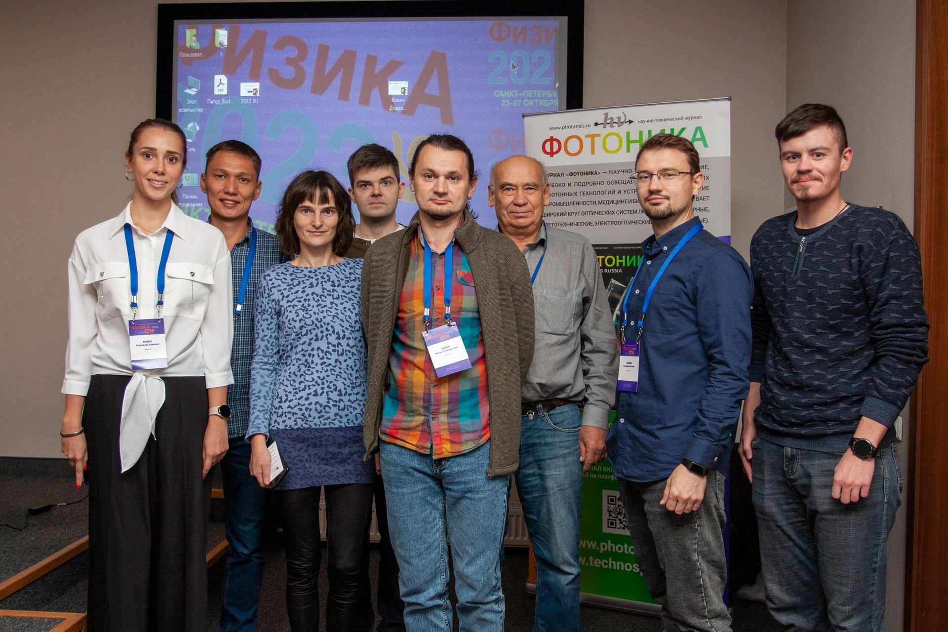
The event has been held since the mid-90s. In recent years, the conference has gathered around 400 participants from various regions of Russia, as well as from near and far abroad. Traditionally, scientists from higher educational institutions and scientific organizations, as well as students and graduate students conducting research in various fields of physics, take part in it.
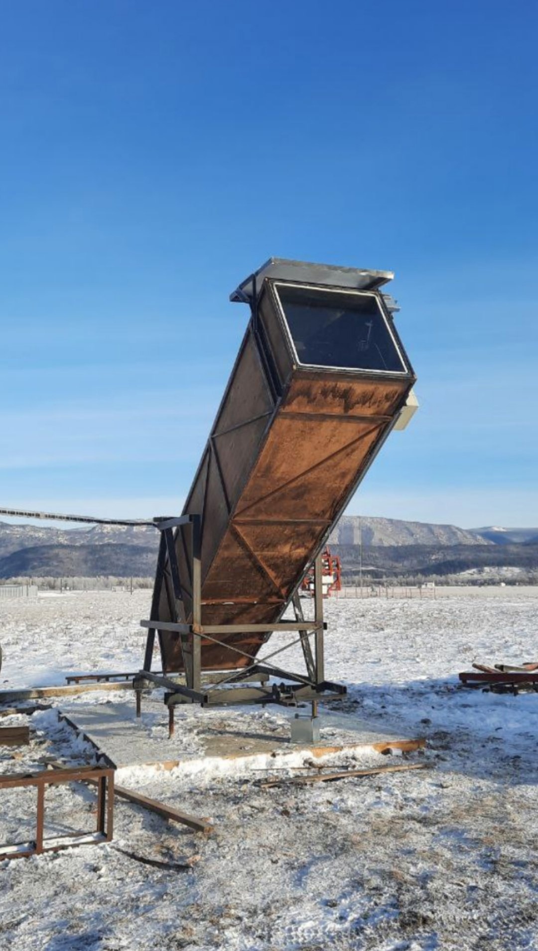
Installation of a fluxmeter on the Tunka-Grande
Until recently, all installations of the TAIGA astrophysical complex ceased operation during thunderstorm activity due to the lack of lightning protection for the detectors.
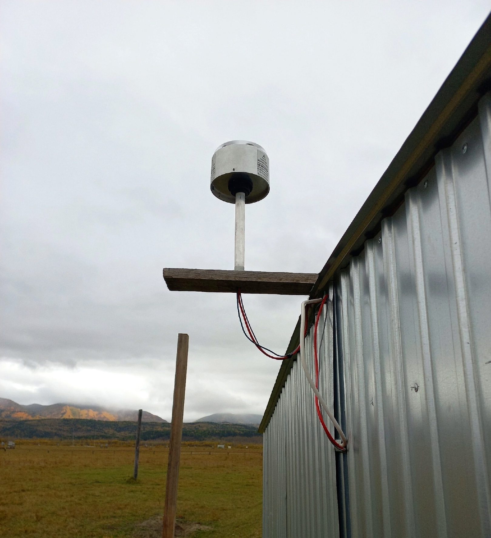
Now, to study the variations in the cosmic ray flux rate during thunderstorms, work has been carried out by API ISU employees to protect one of the Tunka-Grande installation stations and install an atmospheric electric field meter.
The construction of the TAIGA-Muon installation cluster
This year, it is planned to launch 5 such clusters into the set of experimental data.
Photo: Anton Osipov
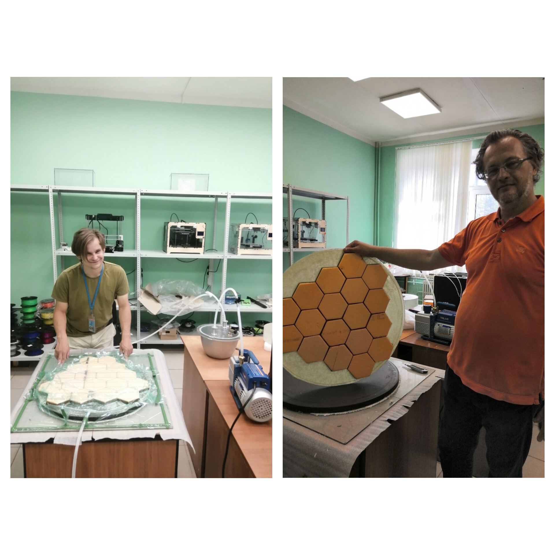
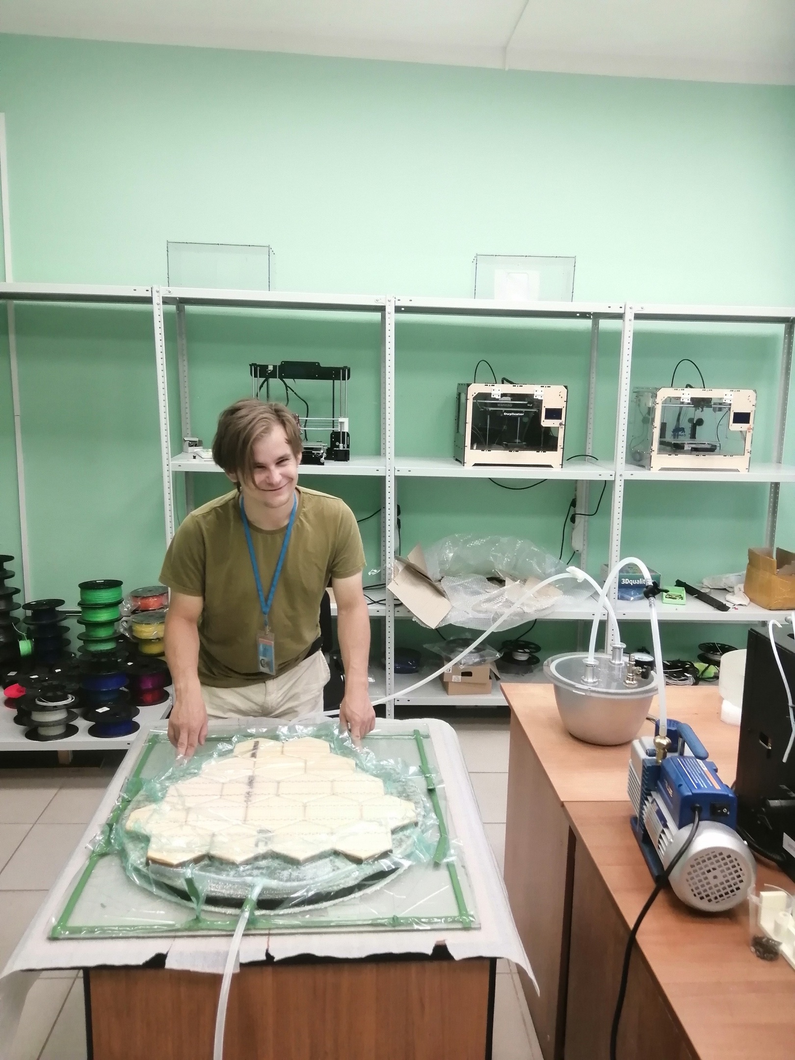
Composite mirror for the TAIGA
In Sector №4 of astrophysical research at NEOFECH DLNP, in collaboration with the Digital Production Center of Dubna State University, a technology has been proposed and a prototype of a lightweight composite mirror for the Cherenkov telescopes of the “TAIGA” project has been manufactured.
Currently, preparations are underway for the subsequent modernization and expansion of detectors to cover an area of about ten square kilometers. The project will include telescopes with a composite mirror diameter of approximately six meters, requiring the production of lightweight composite mirrors. Their manufacture will enable a transition from the traditional process of making monolithic glass mirrors to a faster and more optimal production of a larger number of mirrors for Cherenkov telescopes. Measurements of the mirror parameters, refinement of the technology, and preparation of a proposal to the “TAIGA” collaboration for organizing the production of a batch of mirrors are now being carried out.
Visit of the Russian Minister of Science to familiarize with the TAIGA gamma observatory
The Minister of Science and Higher Education of Russia, Valery Falkov, arrived on a working visit to the Irkutsk region. Together with the Rector of Irkutsk State University, Alexander Fedorovich Schmidt, the Director of the Joint Institute for Nuclear Research, Grigory Vladimirovich Trubnikov, the Director of the ISU Institute of Physics, Andrey Borisovich Tanaev, and the Dean of the ISU Physics Department, Nikolai Mikhailovich Budnev, they familiarized themselves with the TAIGA astrophysical complex located in the Tunka Valley.
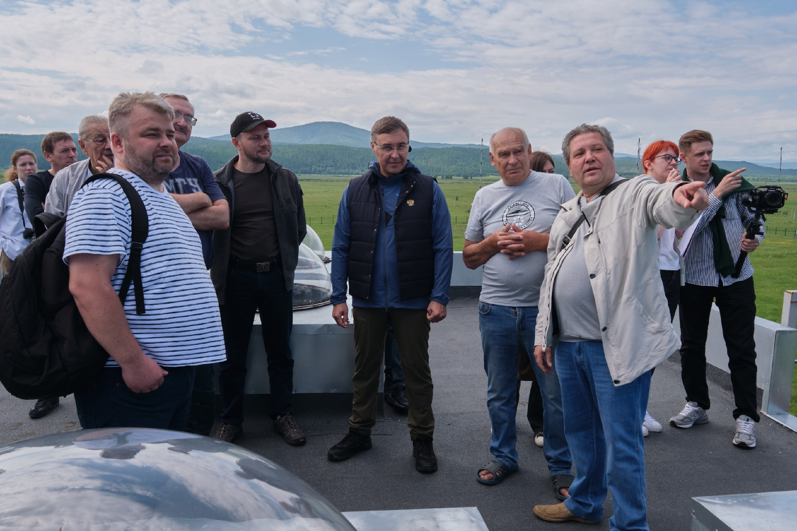
The Minister noted the high quality of the experiment and the significant potential for obtaining new fundamental scientific knowledge.
Photo: Mikhail Ilyushin
58th Session of the JINR Programme Advisory Committee for Particle Physics
On June 21-22, the 58th session of the Programme Advisory Committee for Particle Physics was held at the House of International Conferences of the Joint Institute for Nuclear Research in Dubna. Participants of the event reviewed the results of concluding projects and proposals for opening new ones. As part of the two-day session program, there was a meeting of PAC members with the JINR Directorate and a presentation of poster reports by young scientists.
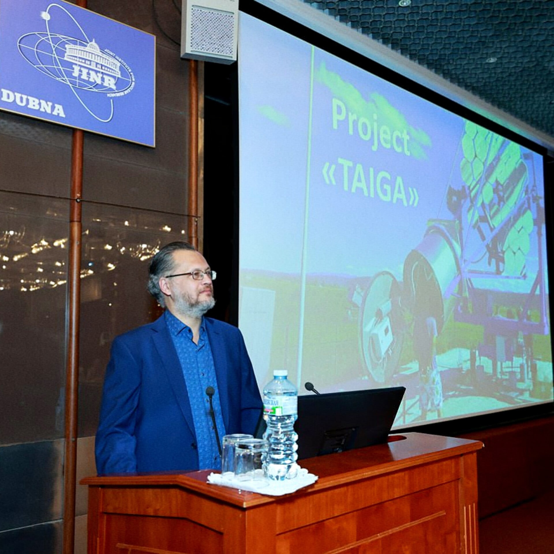
- A report on the TAIGA experiment was presented at this event by Artur Borodin, a member of the V.P. Dzhelepov Laboratory of Nuclear Problems, and the report on the results of the work was prepared by Eduard Boos, Director of the D.V. Skobeltsyn Institute of Nuclear Physics (INR MSU).
- You can find all the necessary information on the event website: indico.jinr.ru/event/3750/
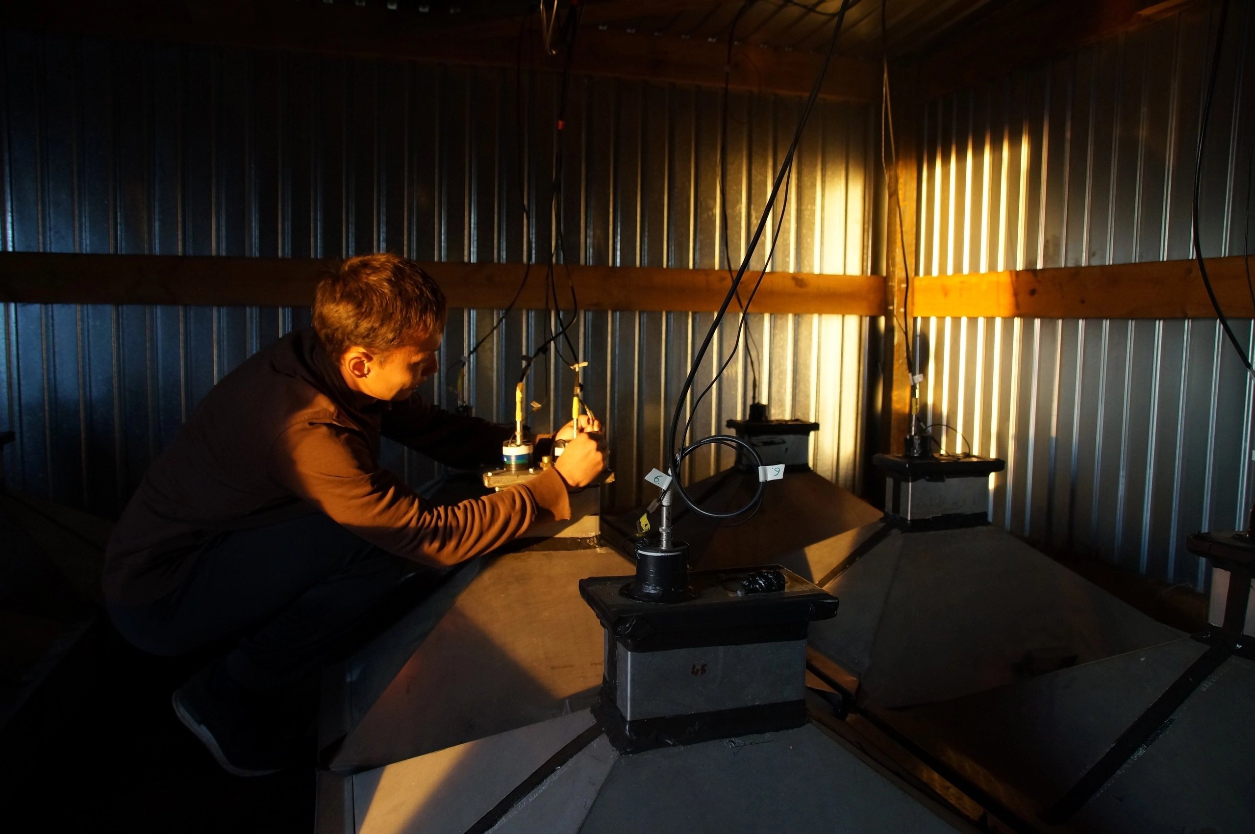
Modernization of the second TAIGA-IACT telescope camera
Students from the Physics Department of ISU, Tomsk University, and employees of the ISU Institute of Physics are coating the Cherenkov camera dividers with lacquer, as shown in the first photo.
TAIGA experiment collaboration meeting
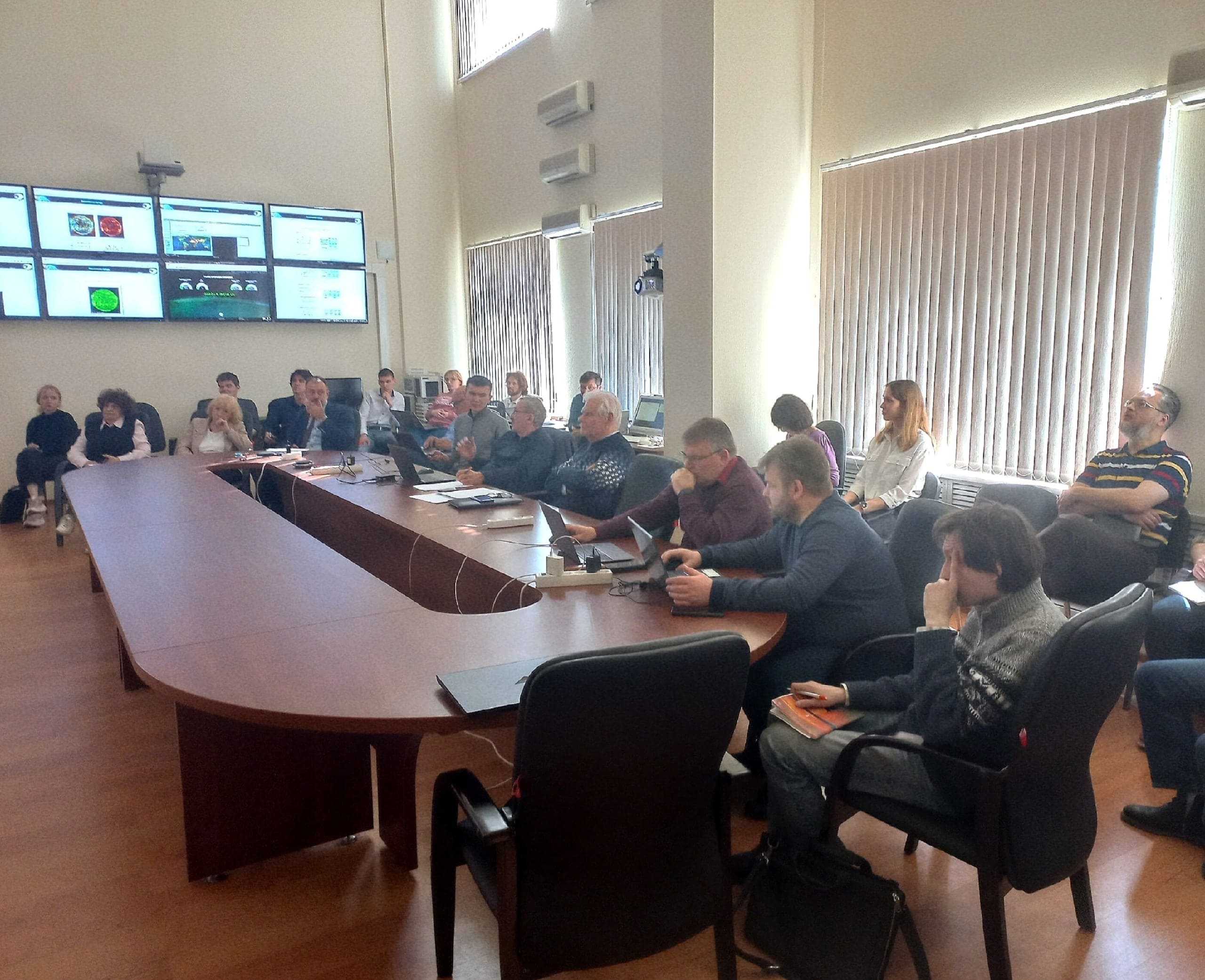
From April 18 to 20, a working meeting of the TAIGA collaboration is being held in Moscow in the conference hall of the High Energy Building of the Institute for Nuclear Research of Moscow State University. Scientists from Moscow, Irkutsk, Dubna, Barnaul, St. Petersburg, and Novosibirsk are participating in the event. During the meeting, the results of the work and plans for the development of the TAIGA experimental complex are being discussed.
Remembering autumn works and preparing for the new construction season
The deployment of the TAIGA-Muon installation cluster by scientific researchers from Irkutsk and Novosibirsk (BINP SB RAS). Currently, the TAIGA astrophysical complex includes 3 clusters of the installation, and it is planned to build 7 more this year.
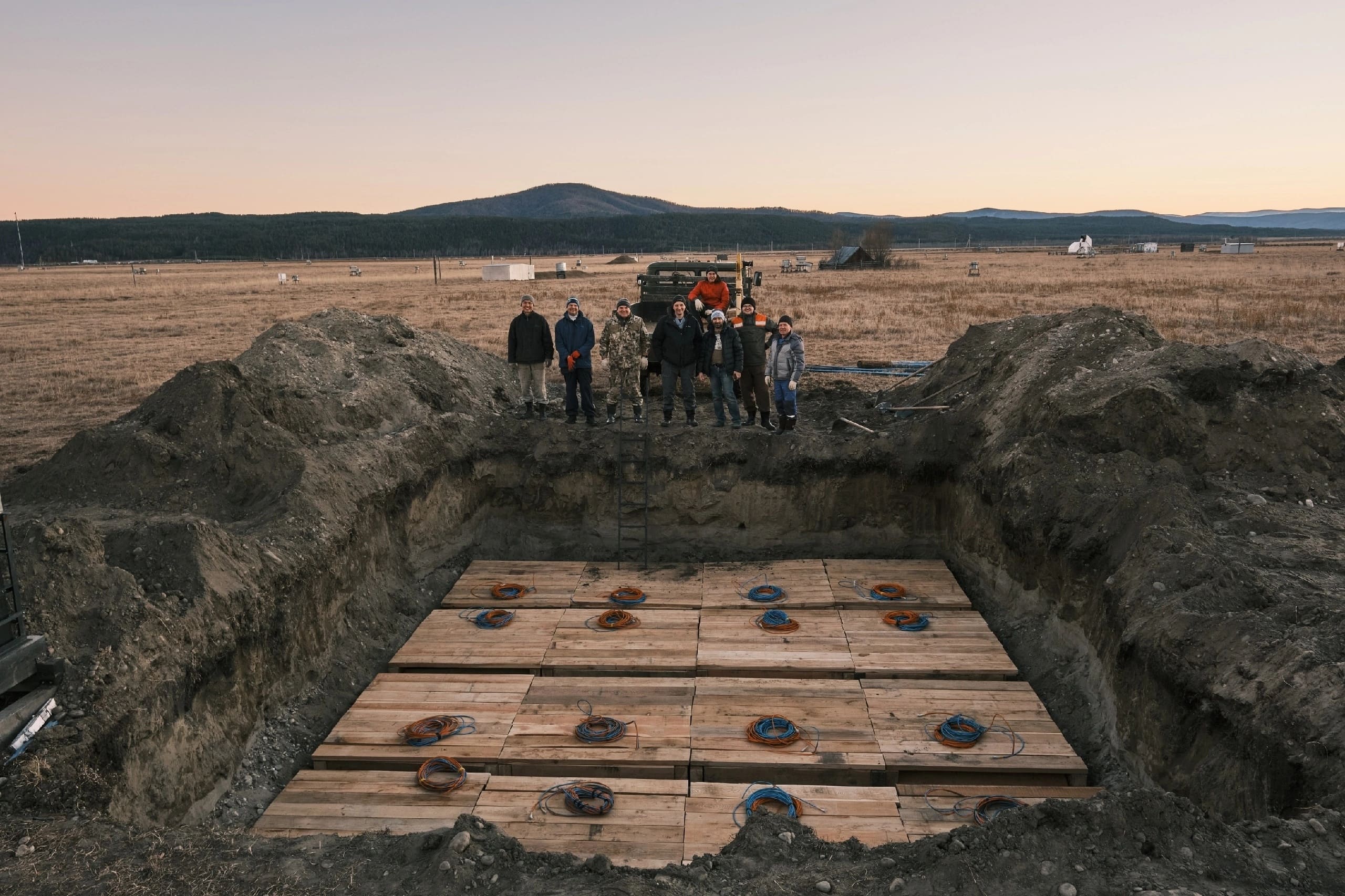
Photo: Mikhail Ilyushin
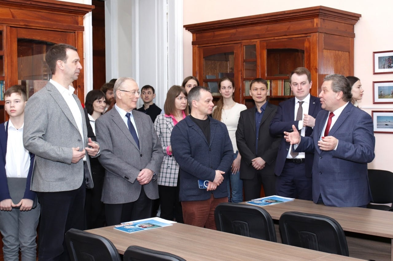
Opening of the JINR information center at ISU
On March 7, in the White House – the center of the former residence of the Governor-Generals of Eastern Siberia – the Information Center of the Joint Institute for Nuclear Research (JINR, Dubna) was opened. For Irkutsk, this place will become a center for the popularization of natural science disciplines. Students, schoolchildren, and their teachers will be able to get acquainted with large-scale projects located in the Tunka Valley and on Lake Baikal – the experimental complex TAIGA and the Baikal neutrino telescope Baikal-GVD, as well as the achievements of Russian and world science.
Already on the day of its opening, the center became a platform for:
- signing an agreement between JINR-ISU-INR RAS (Institute for Nuclear Research of the Russian Academy of Sciences) on the creation of an astrophysical laboratory at ISU
- signing an agreement between ISU-TPU (Tomsk Polytechnic University) on participation in the TAIGA and Baikal-GVD projects
- a lecture by JINR Director Grigory Trubnikov about the NICA project
- the exhibition “Do Science in Dubna”
More details: https://isu.ru/ru/news/2023/details/news-id2023-00117/
2022 year:
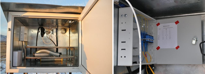
The grounding stations of the Tunka-Grande installation
In October, work began with the creation of lightning protection for the stations of the Tunka-Grande installation to ensure continuous and stable operation of electronics in the summer in conditions of severe thunderstorms.
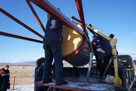
The installation of the 4 telescope of the TAIGA-IACT
In the autumn, at the astrophysical test site, together with the staff of the API ISU and JINR (Joint Institute for Nuclear Research), the body of the fourth telescope of the TAIGA-IACT installation was installed.

The replacement of cable lines the Tunka-133
In the summer, at the astrophysical test site, cable lines were replaced with new ones on 7 clusters of the Tunka-133 facility. Students of the faculty of physics and employees of API ISU took part in the work.
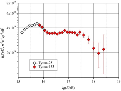
We recall, the installation showed brilliant results. Over 4 years of operation, about 8 million events were registered. The exact form of the resulting energy spectrum turned out to be far from the previously assumed power-law form and is best explained by the acceleration of various nuclei from protons to iron by shock waves from various types of Supernova explosions.
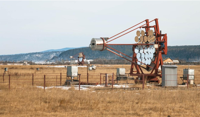
The joint events of the 3 TAIGA-IACT telescopes
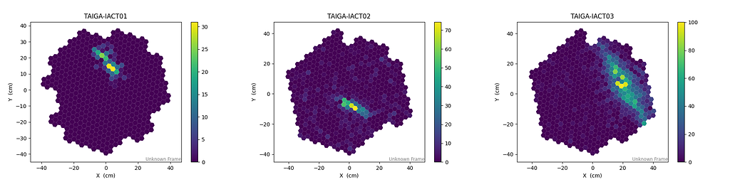
During the launch of the installations in April, the first EASs were registered during the simultaneous operation of the 3 telescopes of the TAIGA-IACT installation.
2021 year:
The new control center for the TAIGA experimental complex was put into operation
The website of the Ministry of Education and Science of Russia published an article about the launch of a new center for monitoring and control of installations of the TAIGA gamma-ray observatory, located at the Tunkinsky astrophysical test site of the ISU: https://minobrnauki.gov.ru/press-center/news/.
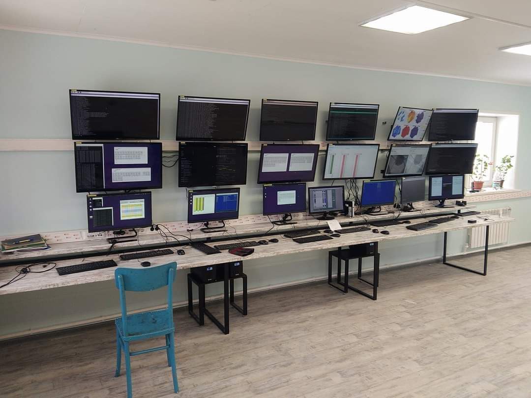
The work on the construction of the building was carried out by the employees of the Research Institute of Applied Physics of the ISU at the expense of funds received within the framework of the federal target program “Research and Development” and the project for the development of unique scientific installations.
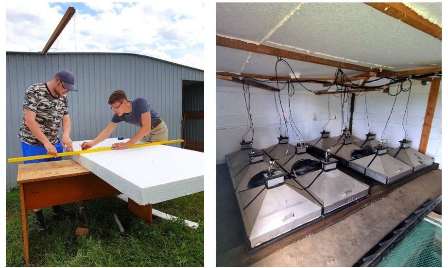
The insulation of the Tunka-Grande stations
In July, the work was launched on the thermal insulation of the Tunka-Grande facility, which in the future will help to avoid condensate in stations and scintillation counters due to large temperature differences. The photo shows students and staff of the Research Institute of Applied Physics of ISU.
2020 year:
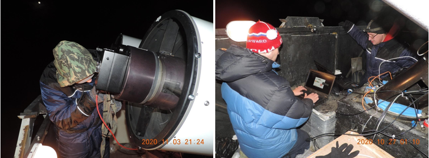
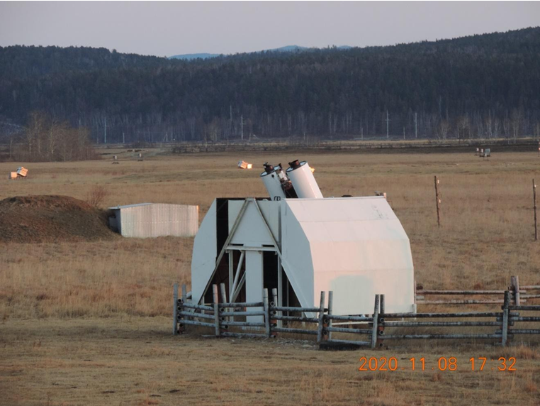
Completion of work on increasing the sensitivity of the MASTER robot telescope, through the creation of a new MASTER-600 robot telescope
The installation of the new MASTER-600 telescope was completed in October-November 2020. The diameter of the telescope is 600 mm, that is, one and a half times higher than the first domestic robot telescope MASTER-400. Aperture 2.1. The photometer is equipped with two QHY 6060 CMOS cameras.
Tests have shown that the domestic robot telescope MASTER-600, which was put into operation, significantly exceeds the capabilities of its predecessor MASTER-400, which formed the basis of the first-generation MASTER Global Network. Recall that the fully robotic high-power wide-field telescopes MASTER are designed to study the most powerful, fast-flowing explosive processes in astrophysics and physics. These objects are sources of hard gamma-ray radiation (gamma-ray bursts), high-energy neutrinos (supermassive black holes), gravitational waves (colliding black holes and neutron stars), and fast radio bursts (of as yet unknown origin). In addition, the unique software allows you to discover new objects of 10 astronomical types: from supernovae to comets and potentially dangerous asteroids. This mathematical software developed by MSU scientists under the guidance of Professor V. M. Lipunov allows almost all the work up to the publication to be carried out in automatic mode.
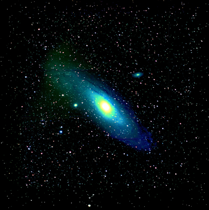
The sensitivity of the telescope increased by 6 times (approximately two stellar magnitudes). Thus, the available volume of the Universe has increased by 15 times, respectively, the efficiency of the Tunka Astrophysical Center for ultrafast optical observations has increased up to 15-20 times, depending on the type of objects. The picture belong shows the first image 5 of the Andromeda galaxy, taken by the new MASTER-600 robot telescope as part of the MSU-ISU Astrophysical Complex.
Completion of the modernization of the Tunka-133 Cherenkov plant in order to increase its effective area to 5 sq. km
In 2020, the following works were completed. The electronics and cable communication lines of the optical detectors were repaired. The main malfunctions are connected with breakages of signal (coaxial) cables, power and control cables, failure of control controllers, voltage dividers, and preamps. Heating controllers (~ 30% of the total number), radio modules (~ 20% of the total number), FADC boards (~ 15% of the total number) were also repaired and replaced on 6 external clusters of the installation.
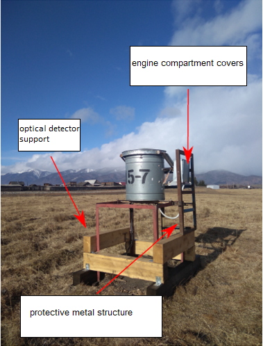
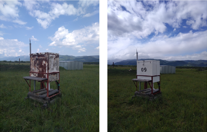
During the summer period of 2020, the supports optical detector by 68% were replaced, 8 engine compartment covers and 7 metal structures were manufactured and installed to replace the faulty ones, in order to protect the optical detectors and cable communication lines from the negative impact from cattle.
In addition, work was carried out to repair all the boxes of the installation electronics, manufacture and install the covers of the transformer compartments inside these boxes.
Thus, as a result of the modernization of the Cherenkov Tunka-133 installation with 100% of the installation electronics and 100% of the optical detectors working properly, its effective area has been increased to 5 square kilometers. At the present time (season 2020-2021), measurement sessions are conducted on a regular basis in accordance with the observation schedules.
Modernization of the TAIGA-HiSCORE installation
In 2020, work was completed on the commissioning of 3 clusters and the full deployment of 4 clusters of the TAIGA-HiSCORE installation consisting of 32 optical stations. The installation of Cherenkov containers and containers for optical station electronics was carried out, the platforms for the stations were filled with sand and gravel mixture, log cabins were assembled, frames were installed, the bodies of Cherenkov containers of optical stations with Winston light-collecting cones and containers for electronics were installed, and the stations were fully equipped with electronics. The 128 R5912 PMF manufactured by Hamamatsu were tested and installed in all 32 optical stations of 4 clusters.
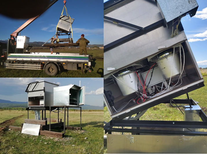
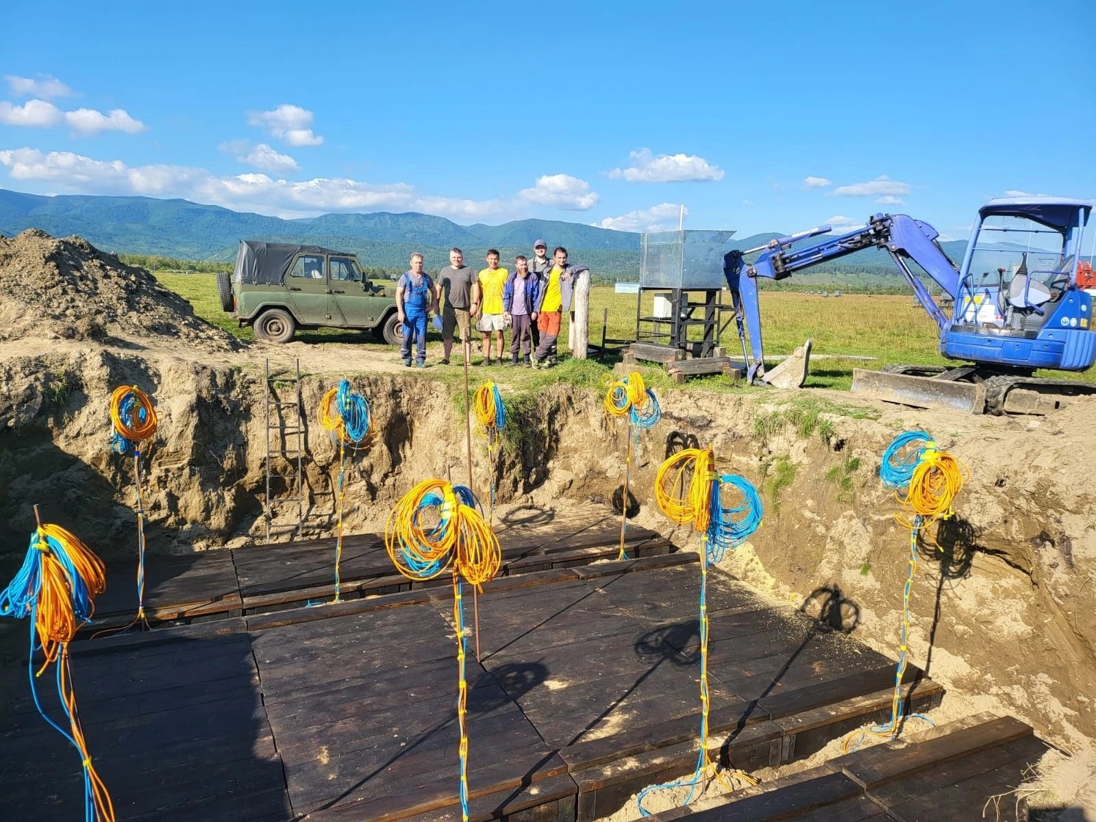
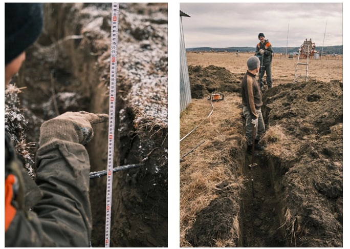
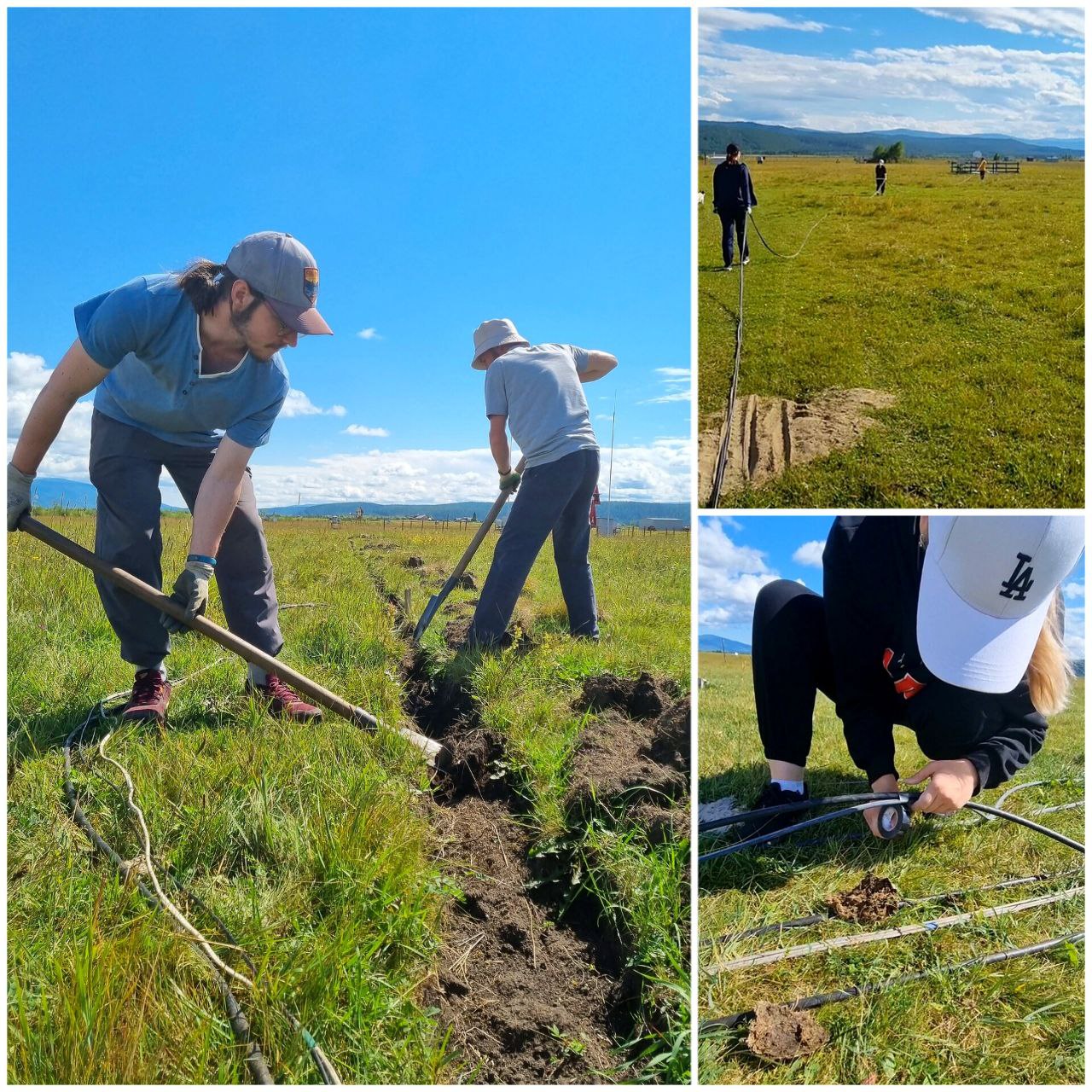
The TAIGA-HiSCORE installation cable communications network was completed. To connect cluster 4 and the third IACT, a power supply line and an optical communication line were laid from the data collection center of the TAIGA gamma-ray observatory pilot complex to the local data collection center of Cluster 4. The work included the following stages:
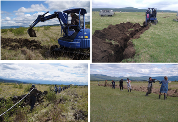
- Geodetic marking of the route. This type of work is necessary for the optimal location of the new power cable on the ground relative to the existing equipment, taking into account the minimum physical and financial costs of carrying out the work;
- Digging a trench with mechanized equipment. The work was carried out by a mini-excavator. The equipment was operated by two people, replacing each other every 3-4 hours.
- In a swampy area, the bottom of the trench is filled with a thick layer of sand.
- Laying the power cable in the trench. This work was performed manually without the use of machinery.
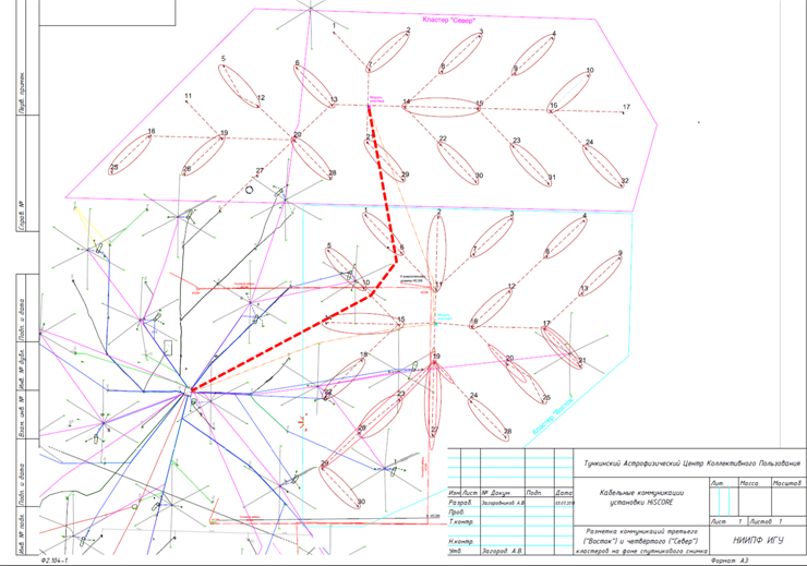
For the transmission of control commands and measurement data, a fiber-optic line is laid for communication over the Ethernet protocol between the center of the 4th cluster and the Central DAQ of the TAIGA Gamma Observatory. Fiber-optic and power cables are also laid from the data collection center of cluster 4 of the TAIGA-HiSCORE installation to all optical stations of this cluster and to the third atmospheric Cherenkov telescope of the TAIGA-IACT installation. All the work on welding of fiber-optic cables at optical stations has been completed.
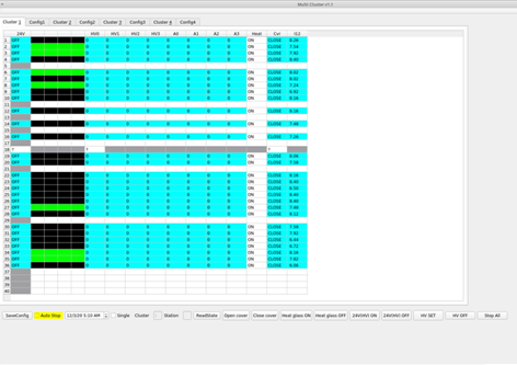
To increase the sensitivity of the TAIGA-HiSCORE installation, when registering sources with different declinations, special mechanisms are installed at all optical stations 3 and 4 of the TAIGA-HiSCORE cluster, which allow changing the inclination of the optical stations relative to the vertical axis. So, to observe the Crab Nebula, the optical stations turn 25 degrees to the south. The drive of the tilt mechanism of the optical station is implemented on a DC motor.
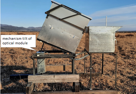
The end positions are limited by the sensors. The tilt system is controlled by the OM controller.
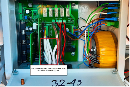
To do this, the controller’s firmware has been modified accordingly. To implement this function, unify it with other programs, and improve the quality of information display, a new program for Linux OS was put into operation. The OM management program for HiSCORE for Windows was created for debugging purposes. In 2021, the rotary mechanisms will be installed on all optical stations 1 and 2 of the TAIGA-HiSCORE cluster.
Thus, in 2020, the deployment of the TAIGA-HiSCORE wide-angle low-threshold Cherenkov installation has been fully completed, the number of its optical stations has reached 120, and the effective area has exceeded a square kilometer, which should more than double the statistics of recorded EAS generated by gamma quanta with an energy above 50 TeV.
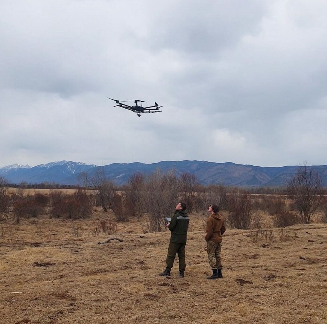
Launching the quadcopter
In April, a trial launch of the Matrice 600 Pro unmanned aerial vehicle was carried out, on board of which there was an LED light source designed for time and amplitude calibration of optical stations and detectors of the TAIGA-HiSCORE and Tunka-133 installations. In the future, it is planned to develop this calibration method and use it not only for wide-angle installations, but also for atmospheric Cherenkov telescopes of the TAIGA-IACT facility.
Modernization of the TAIGA-IACT installation
In January 2020, a camera was installed on the mount of the second IACT of the TAIGA-IACT installation, work was carried out on adjusting the mirrors and calibrating the telescope, after which it was included in the data set.
The second and third telescopes are equipped with hexagonal mirrors, produced by the Italian company MediaLarioS. r. 1. The use of hexagonal mirrors allows you to increase the effective area of the mirror by almost 20%.
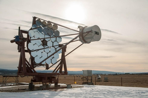
With the commissioning of the second IACT, the possibility of operation of two IACTs of the TAIGA-IACT installation in stereo mode was opened, among other things. Moreover, the distance between IACT1 and IACT2 is about 300 m, which is about three times more than in the VERITAS, H. E. S. S., and MAGIC installations.
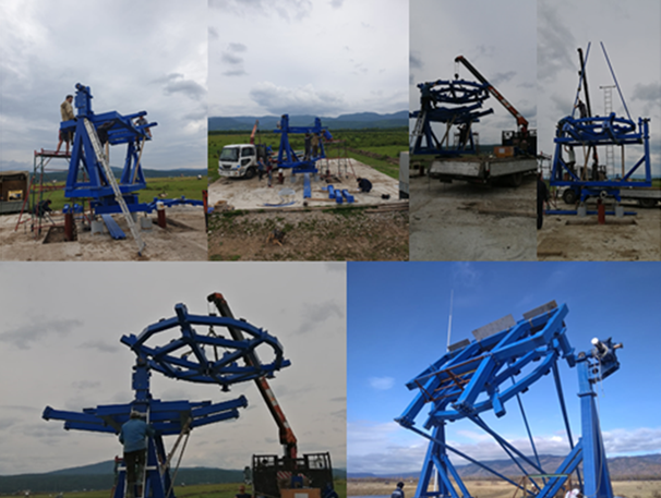
In May 2020, the assembly of the mount of the third IACT of the TAIGA-IACT installation made in the JINR nuclear power plant was carried out.
The following works were also carried out to prepare the third IACT of the TAIGA-IACT installation:
(1) a 2 x 220v power supply line and an optical line for control and data transmission were laid from the data collection center 4 of the TAIGA-HiSCORE cluster to IACT2;
(2) a switchboard for connecting optical and power trunk lines and metal cable channels along the telescope structures and up to the switchboard;
(3) end sensors and encoders for turning the telescope axes were installed, the alignment of the encoder axes was adjusted and a telescope;
(4) the lid of the detector container is manufactured;
(5) cable lines are installed on the telescope structures;
(6) the power supply and heating unit of the telescope detector is mounted and crossed in the electronics container, the power controller, the network switch, the thermal stabilization system are installed, the electronics container on the telescope plate is crossed and switched;
(7) fasteners were made and an electronics container was installed on the telescope fork, a motion controller, network equipment, and a heating controller were installed in it;
(8) the telescope mirrors were installed and adjusted, while a number of problems were solved due to the change in the design of the telescope dish and the fact that MediaLarioS.r.l. (Italy) made mirrors of a hexagonal shape, and not round as on the IACT1, made, mounted, and the system of protection of mirrors from freezing is configured;
(9) a thermally stabilized electronic unit is mounted on the telescope plate, which ensures the distribution of power supply to all nodes of the IACT2 (except for the drive motors of the telescope axes).;
(10) a traverse and slings are made for mounting the camera on the telescope;
(11) containers for balancing the telescope are made and installed; an adjustment screen with a movement mechanism is made.
The power supply of the TAIGA-IACT IACT3 is provided from the AC power supply. For this purpose, a 4x10sq.mm 520m VBSHV cable is laid from the data collection center. The cable is inserted into the container.
There are also optical data transmission lines from the data collection center 4 of the cluster of the TAIGA-HiSCORE installation. Further, communications are laid to the panel for connecting the flexible cable channel trunks.
The flexible cable channel is designed for laying communications between the stationary and rotating parts of the telescope. The flexible cable channel is laid with:
- Power cable 4×2. 5sq. mm;
- Cable for connecting the stepper motor of the vertical axis of the telescope;
- 4-core single-mode fiber optic cable of special design, allowing bending at low temperatures;
- 4 4x-pair Ethernet-Patchcord;
It was planned to install a camera based on semiconductor photodetectors (SiMP) made at the University of Geneva, however, due to the covid-19 pandemic, this was not possible. Currently, the production of an upgraded camera based on the FEU XP 1911 for the IACT3 is being completed. During its manufacture, the following works were performed:
1. a sealed camera body with climate control and daylight protection systems was made;
2. a crate for the camera electronics was made;
3. a matrix for registering the Cherenkov image of the EAS was assembled on the basis of 560 XP1911 FEU equipped with Winston cones;
4. the camera’s read-out electronics were assembled on the basis of ASIC MAROC 3 chips;
5. the camera’s DAG electronics were assembled on the basis of DRS4 chips;
6. the system electronics were assembled control and power supply of the camera;
7. the camera has been debugged, configured, tested, and calibrated.
The camera matrix consists of 560 photomultipliers, which are grouped into clusters. The photomultipliers were pre-calibrated, their main parameters were measured: gain, photocurrent, dark current, etc. Photomultipliers are grouped by the product of their gain and photocurrent. For photomultipliers, the voltages are selected at which the product of the gain on the photocurrent is close to the average photocurrent for all camera photomultipliers multiplied by 10^5.
After all the work is completed, the camera will be installed on the third telescope TAIGA-IACT and the telescope will be switched to data set mode.